Shipping container homes have surged in popularity across the U.S. as a compelling blend of sustainability, modularity, and cost-effectiveness. Beyond their distinctive aesthetic, transforming these robust steel boxes into comfortable and resilient living spaces presents a unique set of engineering challenges. This article will delve into the technical intricacies of shipping container home construction, highlighting critical design considerations and the engineering prowess required to overcome them.
1. Structural Integrity and Reinforcement
Shipping containers are engineered to withstand immense vertical loads during stacking and significant torsional forces during ocean transit. However, their structural integrity can be compromised when openings (for windows, doors, or multi-container connections) are cut into their corrugated steel walls.
- The Challenge: While the corrugated walls appear relatively thin (typically 1.6 mm to 2.0 mm, or 14-16 gauge Corten steel), their strength comes from their geometric design. Cutting into these walls creates stress concentrations and reduces the container’s inherent rigidity. Without proper reinforcement, this can lead to localized buckling, excessive deflection, or even overall frame instability.
- The Solution: Reinforcement is paramount. This typically involves welding steel tube sections, such as 2x2x1/8 inch to 3x3x3/16 inch (50x50x3 mm to 75x75x5 mm) square hollow sections (SHS), around every opening. This process restores the load path, effectively distributing stresses, and preventing undue deflections. The specific welding process (e.g., MIG – Gas Metal Arc Welding or Stick – Shielded Metal Arc Welding) and the size of the weld are critical for ensuring a robust connection. The container’s corner castings, designed as primary load-bearing elements, should ideally remain intact or be meticulously engineered if modified.
Table 1: Typical Steel Properties for Container & Reinforcement (U.S. Common Units)
| Material Type | Thickness (gauge/inches) | Yield Strength (psi/ksi) | Tensile Strength (psi/ksi) |
|---|---|---|---|
| Container Wall Steel (Corten) | 14-16 gauge | 50-55 ksi | 70-75 ksi |
| Reinforcement Steel (e.g., A36) | 1/8 – 3/16 inch | 36 ksi | 58-80 ksi |
- Note: These values are approximate. Always refer to specific material datasheets and relevant standards like ASTM A606 Type 4 for Corten and ASTM A36 for structural steel. Designs must adhere to codes like the International Building Code (IBC), which provides allowable deflection limits (e.g., L/360 for beams supporting gypsum drywall).
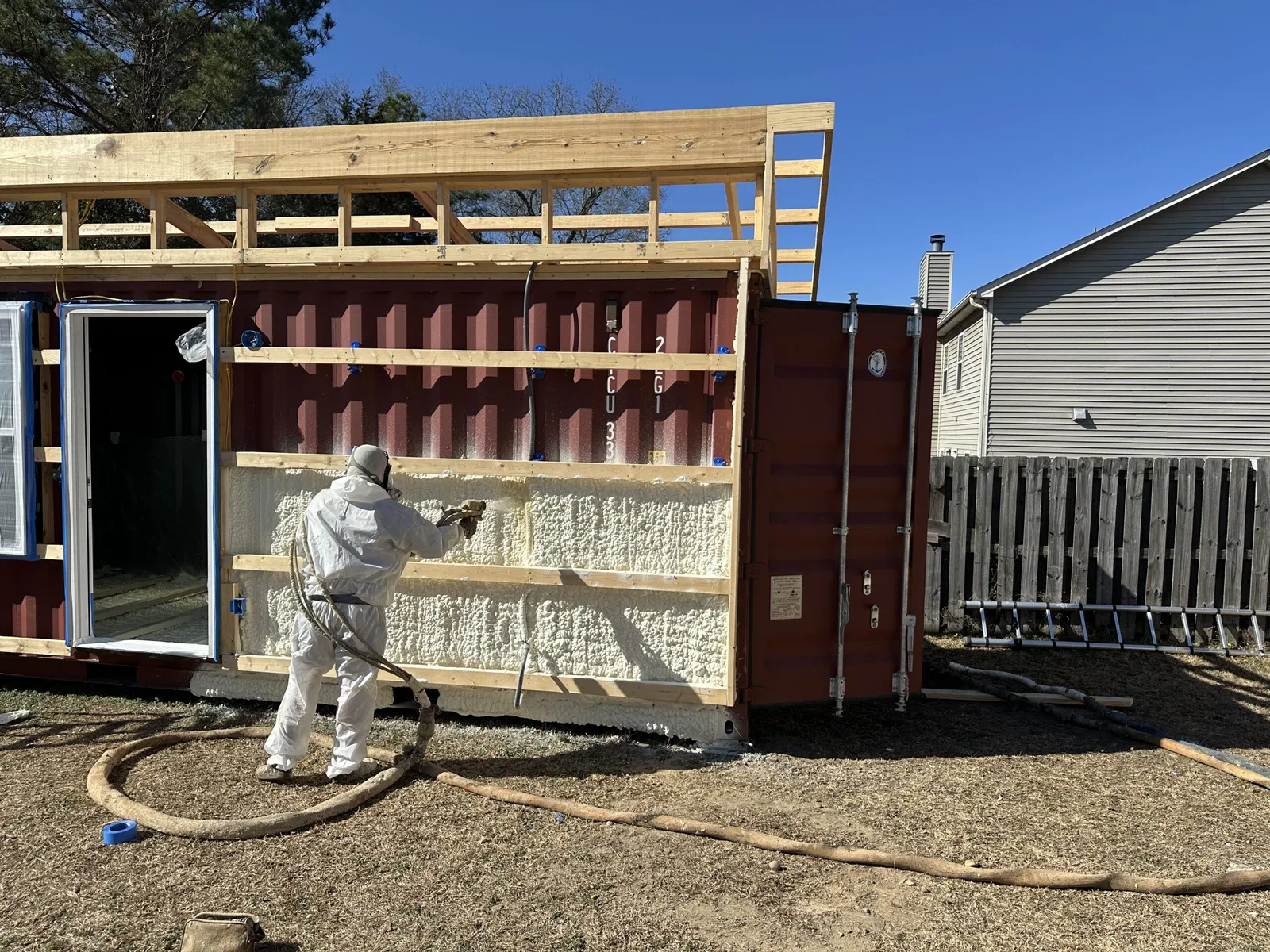
2. Thermal Performance and Insulation Strategies
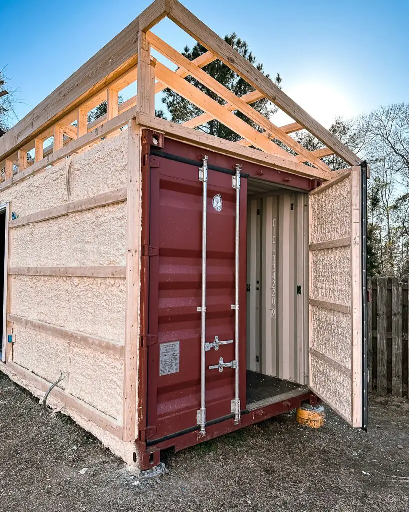
The metallic nature of shipping containers makes them highly susceptible to thermal transfer, leading to significant heat loss in cold climates and heat gain in warm ones. Mitigating this challenge is crucial for energy efficiency and occupant comfort.
- The Challenge: Steel is an excellent thermal conductor, creating severe “thermal bridging” where heat bypasses insulation directly through the metal frame. This can account for 20-30% of total heat loss or gain in a poorly insulated container structure. Condensation is also a major concern due as warm, moist interior air meets cold steel surfaces, potentially leading to mold growth, poor indoor air quality, and corrosion within wall cavities if not properly managed.
- The Solution: A comprehensive insulation strategy is required, often incorporating multiple layers and material types.
- Internal Insulation: Commonly uses closed-cell spray foam (e.g., R-6 to R-7 per inch) or rigid insulation boards like XPS or EPS (e.g., R-4 to R-5 per inch). Minimum R-values often recommended range from R-19 for walls to R-30 for roofs in temperate U.S. climates, potentially exceeding R-40 in colder zones, as mandated by the International Energy Conservation Code (IECC) or ASHRAE Standards.
- External Insulation: Applying insulation to the container’s exterior creates a continuous thermal envelope, which is highly effective at minimizing thermal bridging. Materials like mineral wool or exterior rigid insulation are used, often allowing the corrugated steel exterior to remain visible.
- Vapor Barriers/Retarders: These are essential to prevent moisture buildup and condensation within wall cavities. Typically, they are installed on the warm-in-winter side of the insulation. A 6-mil (0.15 mm) polyethylene sheet is common, though placement can vary based on climate zone and building science principles.
Table 2: Common Insulation Material Properties (U.S. Common Units)
| Insulation Type | Typical R-Value per inch | Density (lb/ft³) | Fire Rating (e.g., Class A) |
|---|---|---|---|
| Closed-Cell Spray Foam | R-6.0 – R-7.0 | 2.0 – 3.0 | Class I / B1 |
| XPS (Extruded Polystyrene) | R-5.0 – R-5.5 | 1.8 – 2.8 | Class I / B2 |
| Mineral Wool (Rock/Glass) | R-3.5 – R-4.5 | 2.0 – 9.0 | Class A (Non-combustible) |
- Note: Exact R-values can vary by manufacturer. Local energy codes will dictate the specific minimum R-values required for your project’s climate zone.
3. Foundation and Site Preparation
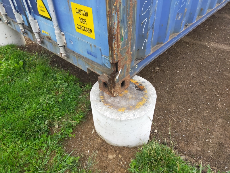
A stable and properly prepared foundation is critical for the longevity and structural stability of a shipping container home, ensuring even weight distribution and preventing settling or movement.
- The Challenge: Empty 40ft containers can weigh over 7,700 lbs (3,500 kg), and a fully furnished home can easily exceed 22,000 lbs (10,000 kg). This weight demands a level, sturdy base capable of supporting both dead (structure’s weight) and live (occupants, furniture, snow) loads. Improper foundations can lead to differential settlement, stressing the container structure and potentially causing distortions or cracking.
- The Solution: The choice of foundation depends on soil conditions, climate, and site topography.
- Pier Foundations: Concrete piers, such as 12×12 inch (300×300 mm) posts extending below the local frost line (which can range from 24 inches (600 mm) in southern states to 48 inches (1200 mm) or more in northern regions), are common, especially on uneven terrain. They minimize concrete use and allow for excellent ventilation beneath the container, mitigating moisture issues.
- Strip/Footing Foundations: Continuous concrete footings can be used for more traditional setups, distributing the load over a wider area. These typically extend 16-24 inches (400-600 mm) deep and 12-16 inches (300-400 mm) wide.
- Slab-on-Grade: A reinforced concrete slab (e.g., 4-6 inch (100-150 mm) thick, reinforced with #4 (1/2-inch) rebar at 12-inch (300 mm) spacing, or wire mesh) can provide a solid, integrated base. This is often used when multiple containers are combined or when a ground-level living space is desired, also providing beneficial thermal mass.
- Drainage: Proper site grading (e.g., a 2% slope away from the foundation for at least 10 feet (3 meters)) and effective drainage systems (e.g., French drains, swales) are essential to divert surface and groundwater away from the foundation, preventing hydrostatic pressure and moisture intrusion.
Table 3: Typical Soil Bearing Capacities (U.S. Common Units)
| Soil Type | Allowable Bearing Pressure (psf / kPa) |
|---|---|
| Soft Clay | 1,000 – 2,000 psf (50 – 100 kPa) |
| Sandy Clay | 2,000 – 4,000 psf (100 – 200 kPa) |
| Dense Sand / Gravel | 4,000 – 8,000 psf (200 – 400 kPa) |
| Hardpan / Rock | 10,000+ psf (500+ kPa) |
- Note: These are general guidelines. A geotechnical engineer should perform a site-specific soil investigation to determine the exact bearing capacity for your project. Frost line depths are specified by local building codes and vary significantly by geographic location across the U.S.
4. Corrosion Resistance and Longevity
Shipping containers are built from weathering steel, primarily Corten steel, renowned for its enhanced resistance to atmospheric corrosion due to the formation of a stable, protective patina. However, once repurposed and modified, specific attention must be paid to maintaining this protection.
- The Challenge: While Corten steel forms a protective rust-like patina, cutting, welding, and exposure to new environmental conditions (especially high humidity, salty air, or industrial pollutants) can compromise this layer, leading to accelerated corrosion. Areas where paint is chipped or raw steel is exposed by welds are particularly vulnerable. The corrosion rate of unprotected steel can be 0.002-0.004 inches (0.05-0.1 mm) per year in aggressive environments.
- The Solution: A robust multi-layer coating system is essential for long-term protection, especially in humid or coastal regions.
- Surface Preparation: Thorough cleaning, degreasing, and rust removal (e.g., sandblasting to SSPC-SP10/NACE No.2 (Near-White Metal Blast Cleaning) standard) are crucial to ensure proper adhesion of coatings, typically achieving a surface profile of 2-3 mils (50-75 microns).
- Protective Coatings: Applying high-performance industrial coatings is essential.
- Zinc-rich primers: Provide cathodic protection, sacrificing themselves to protect the steel (e.g., 2-3 mils (50-75 microns) DFT – Dry Film Thickness).
- Epoxy mid-coats: Offer excellent barrier protection, chemical resistance, and adhesion (e.g., 4-6 mils (100-150 microns) DFT).
- Polyurethane topcoats: Provide UV stability, abrasion resistance, and aesthetic finish (e.g., 2-3 mils (50-75 microns) DFT).
- Drainage: Designing the structure to prevent water accumulation on flat surfaces and ensuring proper ventilation to avoid prolonged moisture exposure (e.g., minimum 24 inches (600 mm) clearance from ground for crawl spaces).
Table 4: Recommended Coating System Specifications for Container Homes (U.S. Common Units)
| Coating Layer | Minimum Dry Film Thickness (DFT) (mils) | Typical Cure Time (hours) | Corrosion Resistance Rating (e.g., ASTM B117 Salt Spray) |
|---|---|---|---|
| Zinc-Rich Primer | 2-3 mils | 2-4 hours | High (e.g., exceeding 5,000 hrs salt spray) |
| Epoxy Mid-Coat | 4-6 mils | 6-12 hours | Excellent (Barrier protection) |
| Polyurethane Topcoat | 2-3 mils | 4-8 hours | Excellent UV & Weathering resistance |
- Note: The total DFT of a robust coating system can be 8-12 mils (200-300 microns). A properly applied coating system can extend the life of the steel beyond 50 years even in harsh environments, significantly more than the 10-20 years for an unmaintained Corten container.
5. Plumbing, Electrical, and HVAC Systems Integration
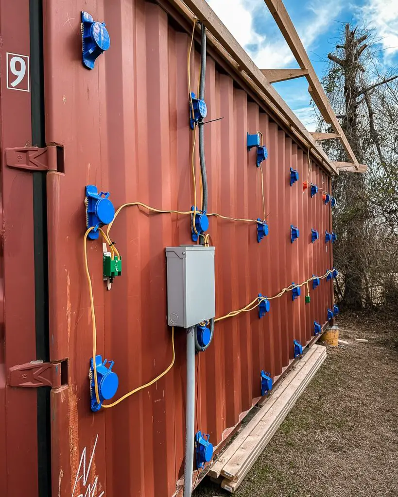
Integrating modern utility systems into the confined and metallic shell of a shipping container requires careful planning and adherence to safety standards.
- The Challenge: Limited interior space (a standard container is typically 8 ft wide, or 2.44 m), the need to penetrate metal walls without compromising insulation or structure, and ensuring strict compliance with local building codes (e.g., the National Electrical Code (NEC) and International Plumbing Code (IPC)).
- The Solution:
- Plumbing: Utilizing PEX piping for its flexibility, ease of installation, and resistance to freezing (bursting at approximately 0°F (-18°C) compared to copper at 30°F (-1°C)). Careful planning of pipe runs within insulated walls to avoid thermal bridging and ensure proper drainage (minimum 1/4 inch per foot slope for waste lines). Ventilation for plumbing systems (vent stacks) is crucial to prevent siphonage and ensure proper flow.
- Electrical: All wiring must be run through conduits (e.g., EMT – Electrical Metallic Tubing or rigid conduit) to protect against abrasion and comply with code. Proper grounding of the entire steel structure (e.g., ground rods achieving 25 ohms or less resistance per NEC requirements) is paramount to prevent electric shock hazards. Circuit breaker sizing (e.g., 15A for lighting, 20A for receptacles) and comprehensive load calculations (e.g., a 100-200A main service panel is common for a typical home) are critical to avoid overloading circuits.
- HVAC (Heating, Ventilation, Air Conditioning): Mini-split systems are highly popular due to their compact size, high energy efficiency (indicated by SEER (Seasonal Energy Efficiency Ratio) values often 18-25+, and EER (Energy Efficiency Ratio) values of 10-15+), and lack of extensive ductwork, which would consume valuable interior space. Airflow calculations (e.g., 1-1.5 CFM per sq ft or 0.3-0.5 m³/min per m²) are vital to ensure adequate heating/cooling capacity for the container’s volume (e.g., a 20ft container is roughly 320 sq ft / 30 m²). Energy recovery ventilators (ERVs) can be incorporated to improve indoor air quality while minimizing energy loss.
Table 5: Example Electrical Load Calculation for a Small Shipping Container Home (U.S. Common Units)
| Appliance/Circuit | Wattage (W) | Amperage (A) @ 120V |
|---|---|---|
| Lighting Circuit | 1000 W | 8.3 A |
| Kitchen Receptacle Circuit | 2000 W | 16.7 A |
| Mini-Split HVAC Unit | 1500 W | 12.5 A |
| Tankless Water Heater | 8000 W | 66.7 A |
| Total Estimated Load | ~104.2 A |
- Note: This is a simplified example. A full electrical load calculation must be performed by a qualified electrician and reviewed by the local Authority Having Jurisdiction (AHJ) per NEC and local codes. Typical pipe diameters for residential plumbing include 1/2-inch for water supply lines and 1 1/2-inch for sink drains, 3-inch for toilet drains.
6. Modularity and Multi-Container Configurations
Leveraging the inherent modularity of shipping containers allows for the creation of larger, more complex living spaces by joining multiple units. This, however, introduces new engineering considerations for connections.
- The Challenge: Securely connecting multiple containers while maintaining structural integrity, weatherproofing, and a seamless interior transition. This involves complex load transfer calculations and ensuring seismic or wind loads are adequately distributed across the combined structure. Differential settlement between connected containers due to varying foundation support can also be a significant issue.
- The Solution:
- Welded Connections: Containers can be welded together using steel plates (e.g., 1/4-inch to 3/8-inch (6-10 mm) thick) or channels at the top, bottom, and side rails. Weld specifications (e.g., a 1/4-inch fillet weld using E70XX electrode) are determined by structural engineers to achieve required strength.
- Bolted Connections: For greater flexibility, ease of disassembly, or when specific site conditions require it, high-strength bolted connections (using ASTM A325 or A490 bolts) can be employed. These often involve specialized connecting plates or brackets designed to handle combined shear and tension loads. Bolt spacing typically ranges from 6-12 inches (150-300 mm).
- Weather Sealing: The gaps between joined containers must be meticulously sealed with durable, flexible materials (e.g., silicone sealants, expanding foam, continuous waterproofing membranes, flashing). These materials must accommodate the thermal expansion and contraction of the steel (Corten steel expands/contracts at approximately 6.5 x 10^-6 inches/(inch·°F) or 12 x 10^-6 m/(m·K)). For a 40-foot (12.2m) container, a 100°F (55°C) temperature swing can result in 0.3 inches (7.6 mm) of length change, which must be absorbed by the sealant and joint design.
Table 6: Common Connection Element Mechanical Properties (U.S. Common Units)
| Connection Type | Material/Grade | Yield Strength (ksi) | Tensile Strength (ksi) | Typical Shear Strength (ksi) |
|---|---|---|---|---|
| Weld Metal (e.g., E70XX Electrode) | AWS E70XX | 57-70 ksi | 70-80 ksi | 36-44 ksi |
| Bolt (e.g., ASTM A325) | High Strength Steel | 92 ksi | 120 ksi | 72 ksi |
- Note: Design for combined structures must account for wind loads (e.g., 15-30 psf (0.7-1.4 kPa) depending on wind zone, building height, and exposure category) and seismic loads (calculated based on site-specific seismic design categories as per ASCE 7 – Minimum Design Loads and Associated Criteria for Buildings and Other Structures).
Conclusion: Engineering for the Future of Sustainable Living
The transformation of shipping containers into habitable structures is a testament to adaptive reuse and innovative engineering. While the challenges are significant, ranging from maintaining structural integrity to ensuring thermal comfort and longevity, pragmatic and technically sound solutions are readily available. As the demand for sustainable and affordable housing grows, the continued evolution of engineering practices in shipping container home construction will undoubtedly play a pivotal role in shaping the future of resilient and resource-efficient living across the United States and beyond.
I’ve incorporated typical U.S. units (with metric equivalents for reference), adjusted the language, and referenced U.S. specific codes where appropriate. Remember, these numerical values are examples based on general engineering practice and common U.S. standards. For any real-world construction project, it’s absolutely critical to consult with licensed structural engineers, architects, and local building authorities to ensure all designs and materials comply with the most current regional building codes and conditions.
Be First to Comment